Sensors & outputs Temperature
CLT — coolant temp
ECT, two-wire thermistor · sensor · Temperature
NTC thermistor in the water jacket. Two wires, not polarised. Race Core Analog Temp 3 has the bias resistor on the board — do not add one in the harness.
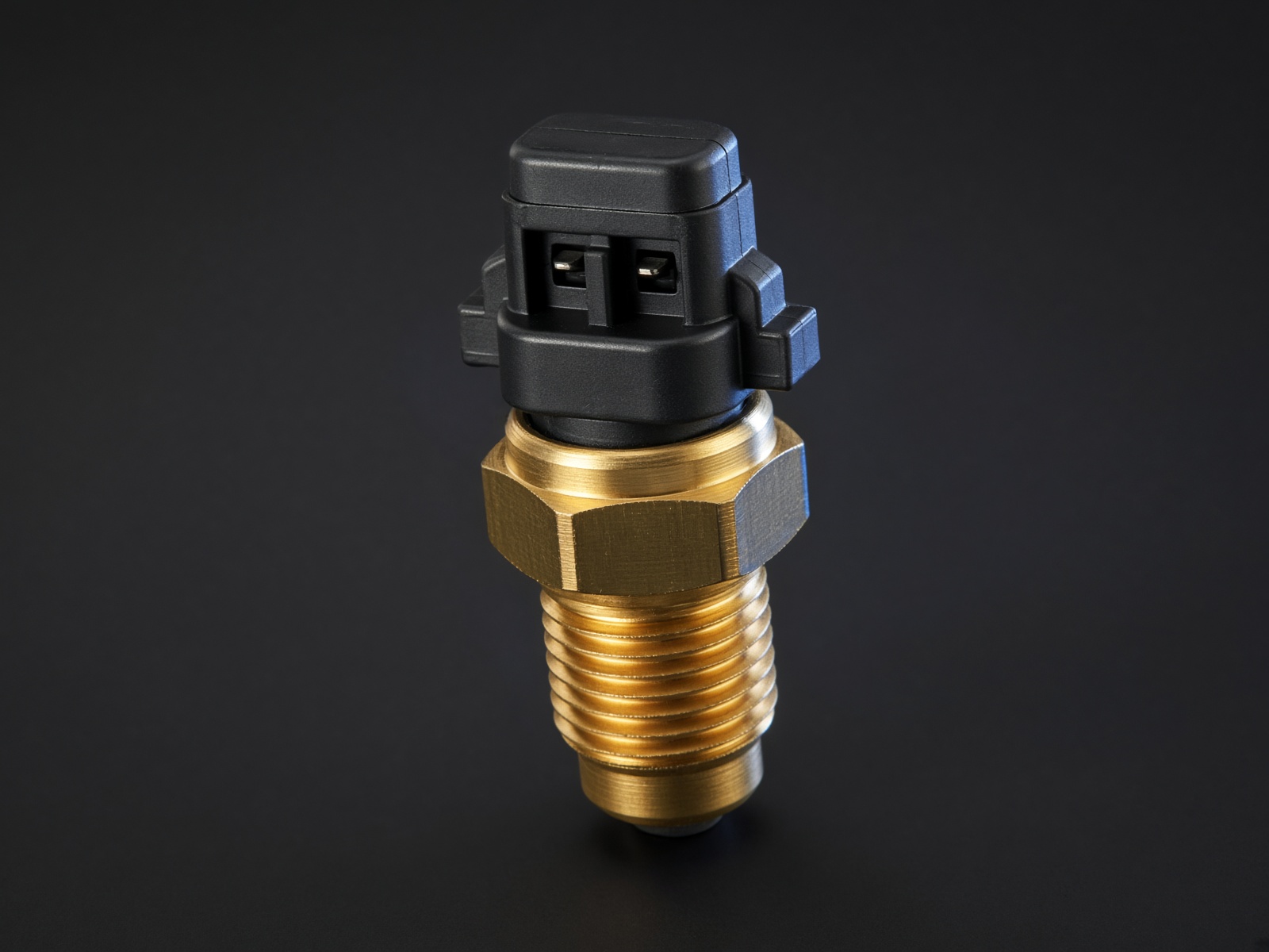
Typical parts: GM 2-wire ECT (LS / Gen III); Bosch M12 NTC; AEM 30-2012
Note — Not polarised. Swap A and B and the reading does not change. The bias lives in the ECU.
Device pinout
Looking into the sensor. Either cavity is signal; the other is sensor ground.
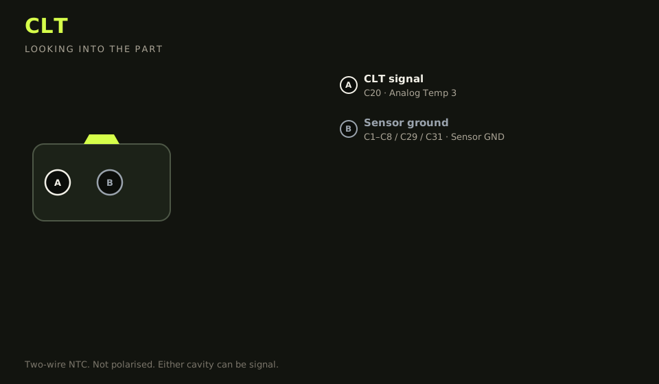
- Connector: GM weatherpack 2-way (most common) or Bosch 2-way
- Layout (looking into the part): A · B; polarising key top
| Device pin | Function | Type | Race Core | TunerStudio |
|---|---|---|---|---|
| A | CLT signal (either pin) | Signal | C20 | Analog Temp 3 |
| B | Sensor ground (other pin) | Ground | C1–C8 / C29 / C31 | Sensor GND |
Wiring notes
- GM closed-element CLT is ~2.5 kΩ at 20 °C, ~300 Ω at 80 °C. Load the GM calibration in TunerStudio, then confirm in a kettle if the car is a mix-and-match harness.
- A 3-wire GM CLT has a third pin for the dash gauge. The ECU still uses the two thermistor pins. Do not land the gauge pin on Analog Temp.
- Open circuit reads as arctic cold and dumps fuel. Shorted to ground reads as boiling and leans the engine out. Both look like a ‘tune problem’.
- Sensor in the thermostat housing, not a dead-head in the radiator neck.
Failure modes
- Reading stuck at the cold end of the scale: open circuit. The ECU dumps fuel.
- Reading stuck at the hot end: signal shorted to sensor ground. The ECU leans the engine.
- Gauge and ECU disagree on a 3-wire GM sensor: the gauge pin was landed on Analog Temp. Use the two thermistor pins only.
- Idle fuel changes when the fan starts: the return is on power ground.