Sensors & outputs Ignition
Coil — LS truck D585
Logic COP, LS2 truck coil · output · Ignition
4-pin 5 V logic coil-on-plug. Race Core ignition pins are 5 V push-pull — they will not ground a dumb coil. Wire Ign n to cylinder n; firing order is software.
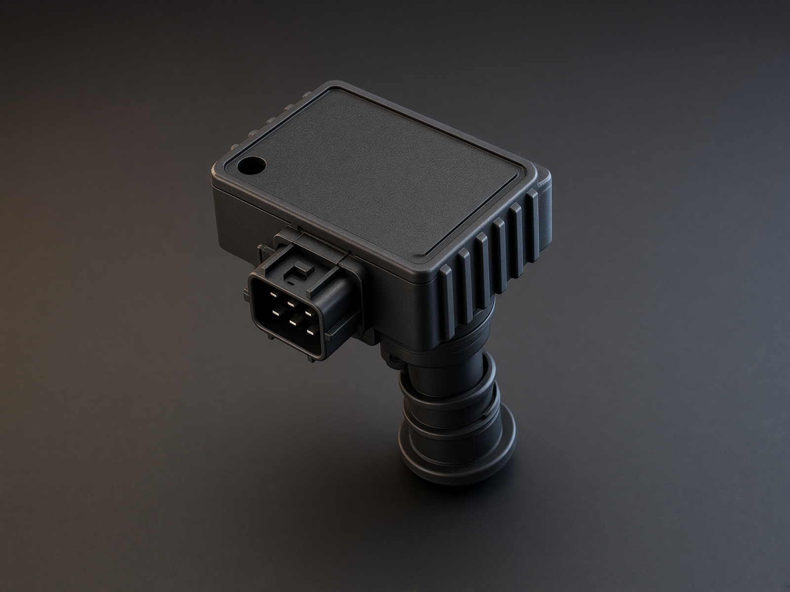
Typical parts: GM D585 / 10457730 truck; GM D581; LS3 / LSA pencil with built-in igniter
Warning — Logic only. Race Core Ign pins will not fire a dumb coil. No igniter in the coil means no spark, and eventually a dead ignition pin.
Device pinout
Looking into the coil, latch at the bottom. Pins A · B · C · D left to right as stamped.
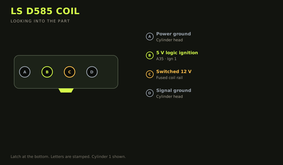
- Connector: GM 4-way on the coil. Letters are stamped on the housing.
- Layout (looking into the part): A · B · C · D; polarising key bottom
| Device pin | Function | Type | Race Core | TunerStudio |
|---|---|---|---|---|
| A | Power ground (head) | Ground | Cylinder head stud | — |
| B | 5 V logic trigger (cyl 1 shown) | Ignition | A35 | Ign 1 |
| C | Switched 12 V (coil rail) | 12 V | Fused coil 12 V rail | — |
| D | Signal / power ground (head) | Ground | Cylinder head stud | — |
Wiring notes
- Cylinder order: Ign 1 A35, Ign 2 A34, Ign 3 A22, Ign 4 A33, Ign 5 A32, Ign 6 A31, Ign 7 A30, Ign 8 A29.
- D580 / early LS1 coils are reversed end-for-end versus D585. Meter 12 V vs ground on the coil you have before you apply a signal. Applying 12 V to a ground pin lets the magic smoke out of the igniter.
- Dwell 2.5–3.0 ms running. They run hot at 5 ms, or if the ground is a painted body panel.
- Fuse the coil 12 V rail 10–15 A. Coil ground is the head, not sensor ground.
Failure modes
- No spark and an ignition pin that no longer toggles: a dumb coil was hung on a logic output.
- Spark on the wrong cylinder: the coil harness was wired in firing order. Wire Ign n to cylinder n.
- Coils too hot to touch after a short idle: dwell past about 3 ms, or the head ground is paint.