Sensors & outputs Knock
Knock
Piezo knock sensor · sensor · Knock
Resonant piezoelectric puck. Two-wire, shielded. Race Core Knock 1 / Knock 2 are dedicated inputs — not Analog Volt.
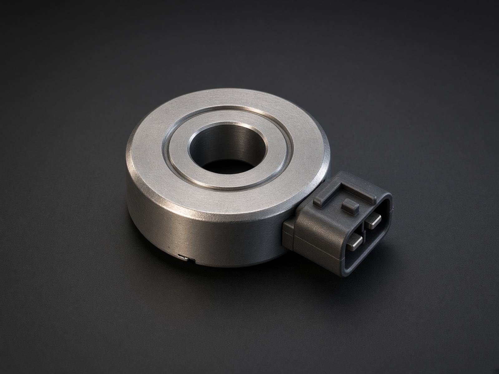
Typical parts: GM LS knock (one per bank); Bosch resonant knock; Nissan VQ knock
Note — Bolt is the ground. Many OEM pucks return through the block. Still run the dedicated − wire; do not rely on paint.
Device pinout
Looking into the sensor. Signal and return; polarity is usually marked + / − or not at all.
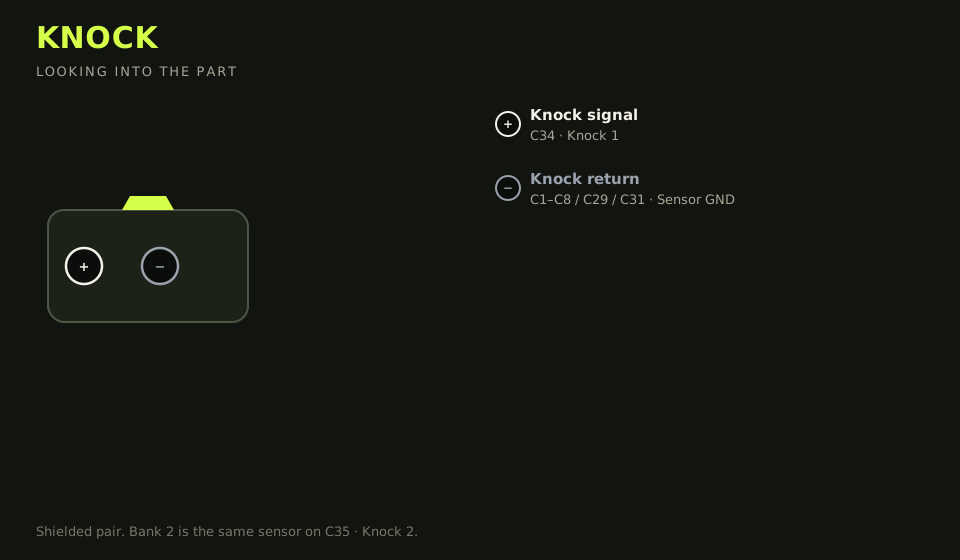
- Connector: 2-way on the sensor. Case is often a third ground through the bolt.
- Layout (looking into the part): + · −; polarising key top
| Device pin | Function | Type | Race Core | TunerStudio |
|---|---|---|---|---|
| + | Knock signal bank 1 | Signal | C34 | Knock 1 |
| − | Knock return | Ground | C1–C8 / C29 / C31 | Sensor GND |
Wiring notes
- Bank 2 is the same sensor on C35 (Knock 2).
- Shielded pair. Shield to sensor ground at the ECU end only. Keep the run away from coil and injector wiring.
- Torque the bolt to the sensor spec (often ~20 N·m). A loose knock sensor is a deaf knock sensor. Thread-lock is not a substitute for torque.
- Do not land a knock sensor on Analog Volt. The input is not a 0–5 V ratiometric part.
Failure modes
- Knock voltage sits at a rail: the sensor is on Analog Volt, or the return is open.
- Knock noise follows rpm in a smooth curve and ignores real ping: the wire is next to a coil.
- A freshly installed sensor stays deaf: the bolt is under-torqued, or the washer stack is wrong. Torque to the sensor spec.