Sensors & outputs Trigger
VSS — speed
Hall vehicle speed, GPS pulse · sensor · Trigger
Hall or GPS-pulse speed input. Default Digital 3. Used for traction, gear detection, and logging. A 2-wire VR VSS belongs on a VR input, not here.
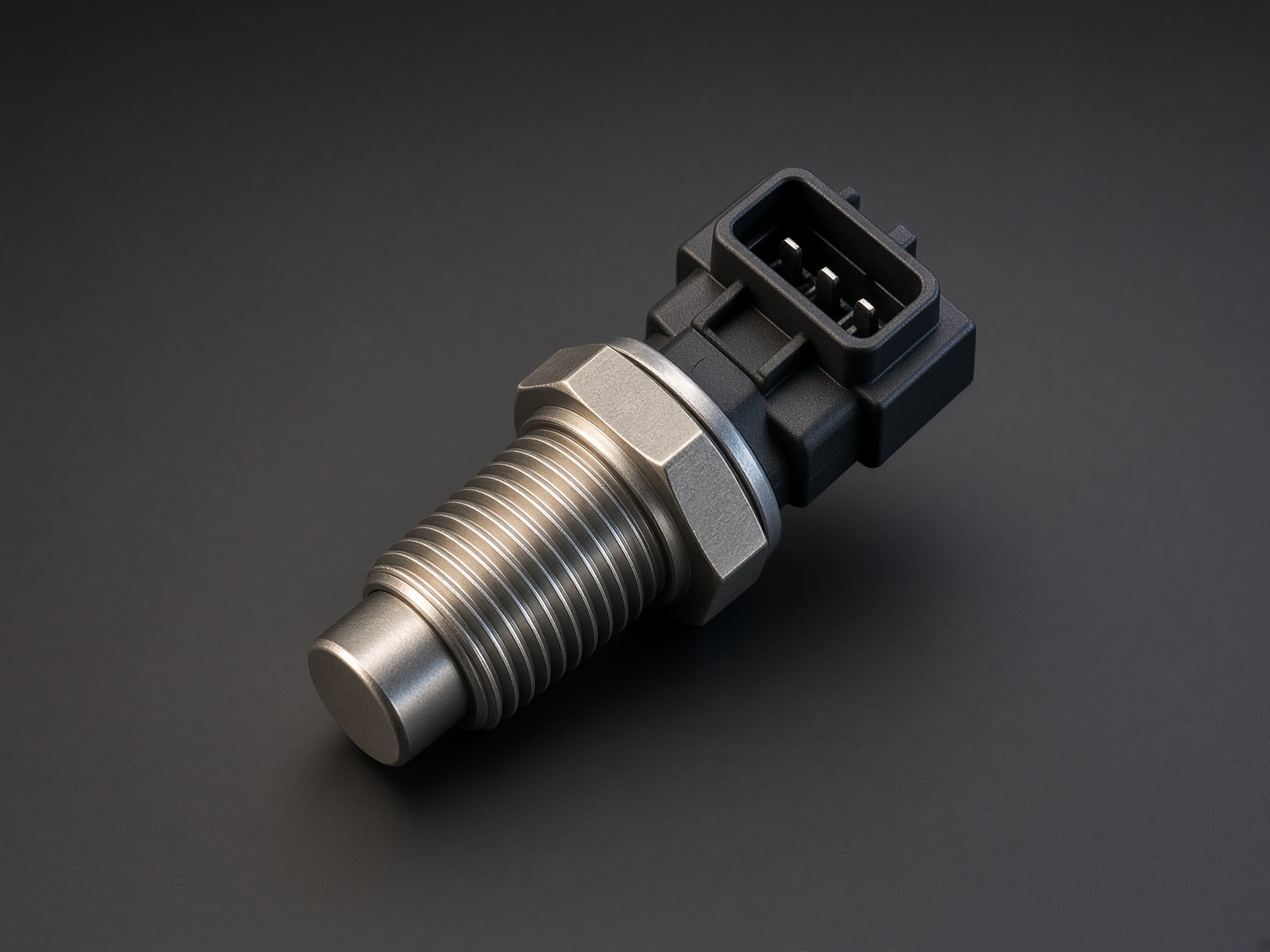
Typical parts: GM 3-wire Hall VSS; Acewell ACUK-SGPS pulse GPS; Honeywell Hall proximity
Device pinout
Looking into a 3-wire Hall sensor, locking tab at the top.
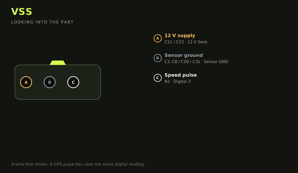
- Connector: 3-way Hall, or a 12 V pulse box (GPS)
- Layout (looking into the part): A · B · C; polarising key top
| Device pin | Function | Type | Race Core | TunerStudio |
|---|---|---|---|---|
| A | 12 V supply | 12 V | C11 / C23 | 12 V Sens |
| B | Ground | Ground | C1–C8 / C29 / C31 | Sensor GND |
| C | Speed pulse | Signal | B2 | Digital 3 |
Wiring notes
- GPS pulse boxes (Acewell-style 5,000 pulses/km, 12 V square) land the pulse on Digital 3, 12 V from the box’s own supply, common ground with the ECU. Set pulses per km in TunerStudio.
- If Digital 3 is flex fuel, use Digital 5 (B9) for VSS.
- Pull-up on for open-collector Hall. Pull-up off if the box is already a push-pull 12 V pulse.
- ABS tone-ring VR sensors are 2-wire — that is the VR page, not this one.
Failure modes
- Speed stuck at 0 with the wheels turning: pull-up is off on an open-collector Hall, or the pulse is on a VR input.
- Speed doubles: both edges are counted. Use one edge.
- Flex fuel and speed fight over one channel: Digital 3 cannot be both. Move VSS to Digital 5 (B9) or flex to Digital 4 (B3), and write it on the lid.