Wideband
LSU 4.9 / analog AFR / CAN AFR · sensor · AFR
The probe is not an analog sensor. A Bosch LSU 4.9 needs a controller. Preferred path on Race Core is CAN on CAN 1. Analog 0–5 V is Analog Volt 5 if the controller has no CAN.
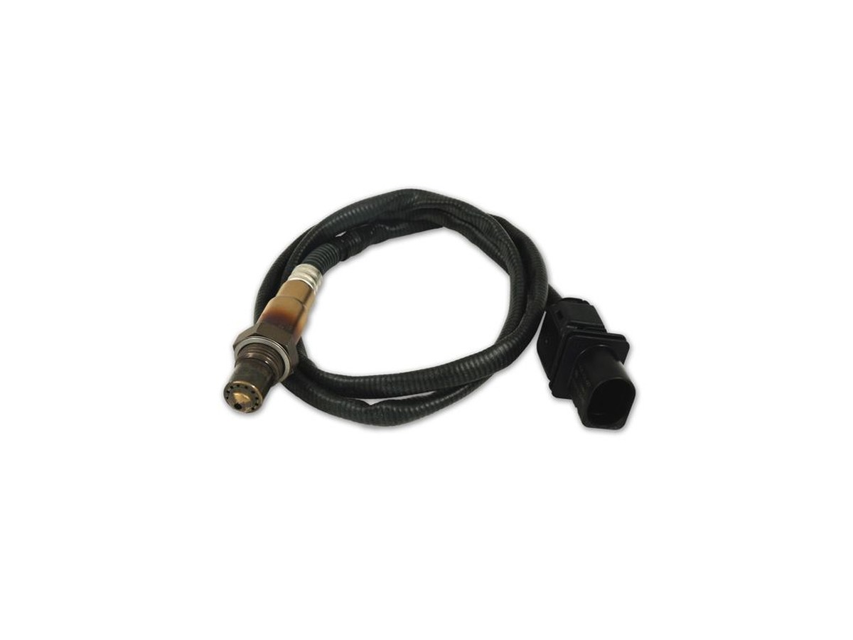
Typical parts: Bosch LSU 4.9, 0 258 017 025 family; AEM X-Series (CAN or analog); Innovate LC-2 analog; DStage AFR controller
Warning — Not an analog input. Six LSU wires into Analog Volt 5 will not read AFR and can damage the input. Use a controller, or CAN.
Device pinout
LSU 4.9 looking into the sensor connector, polarising key at the top. Do not land these pins on Analog Volt.
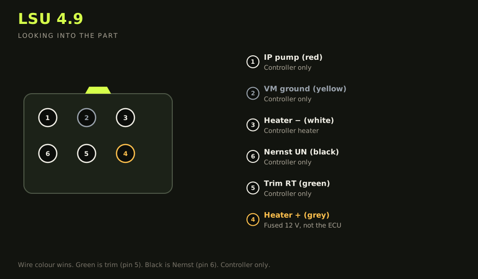
- Connector: Bosch 6-way on the LSU. Analog out is on the controller, not the probe.
- Layout (looking into the part): 1 · 2 · 3 / 6 · 5 · 4; polarising key top
| Device pin | Function | Type | Race Core | TunerStudio |
|---|---|---|---|---|
| 1 | IP+ pump current (red) | Signal | Controller only | — |
| 2 | VM virtual ground (yellow) | Ground | Controller only | — |
| 3 | Heater − (white) | Low-side | Controller heater | — |
| 4 | Heater + (grey) | 12 V | Fused 12 V on main-relay output | — |
| 5 | Calibration resistor RT (green) | Signal | Controller only | — |
| 6 | Nernst UN (black) | Signal | Controller only | — |
Wiring notes
- Analog path: controller analog out → C15 (Analog Volt 5). Analog ground → sensor GND. Set the same 0–5 V AFR scale in TunerStudio as the controller (Innovate 10–20, AEM X-Series 8.5–18, and so on).
- CAN path: controller on CAN 1 (B17 H / B16 L), 1 Mbit/s, one extra terminator only if the controller is an end node. This is the default for Race Core devices.
- Heater current is several amps. Fuse 5–10 A on the main-relay output. The heater does not run through the ECU.
- Bung in the collector, before the cat, 10 o’clock or 2 o’clock — not the bottom where it drowns on shutdown.
- Bosch connector colours: pin 1 red IP, pin 2 yellow VM, pin 3 white heater −, pin 4 grey heater +, pin 5 green trim, pin 6 black Nernst. Pin 5 and pin 6 are not interchangeable.
- The trim resistor lives in the connector. Cutting it out and “just using the five sensor wires” loses the calibration.
- A DStage-style controller uses the analog landing on this page. Its harness labels are on the DStage AFR note.
Failure modes
- Analog Volt 5 sits at a rail while the controller looks alive: analog ground is open, or the narrowband simulation was landed instead of the wideband output.
- Free air reads as a rich AFR: the TunerStudio scale does not match the controller.
- Heater never finishes: grey (pin 4) is not on fused 12 V, or white (pin 3) never reaches the controller.
- Lambda is noisy and slow: green (pin 5, trim) and black (pin 6, Nernst) are swapped. The connector resistor has to stay in the circuit.