Sensors & outputs Pressure
Bosch P+T
Combined pressure and temperature · sensor · Pressure
One bung, two measurements. The fluid sensors in the Bosch PST-F family put a ratiometric 0–5 V pressure signal and an NTC temperature signal on a trapezoid connector. Race Core can take the pressure today. The temperature landing is not in the published F7 map.
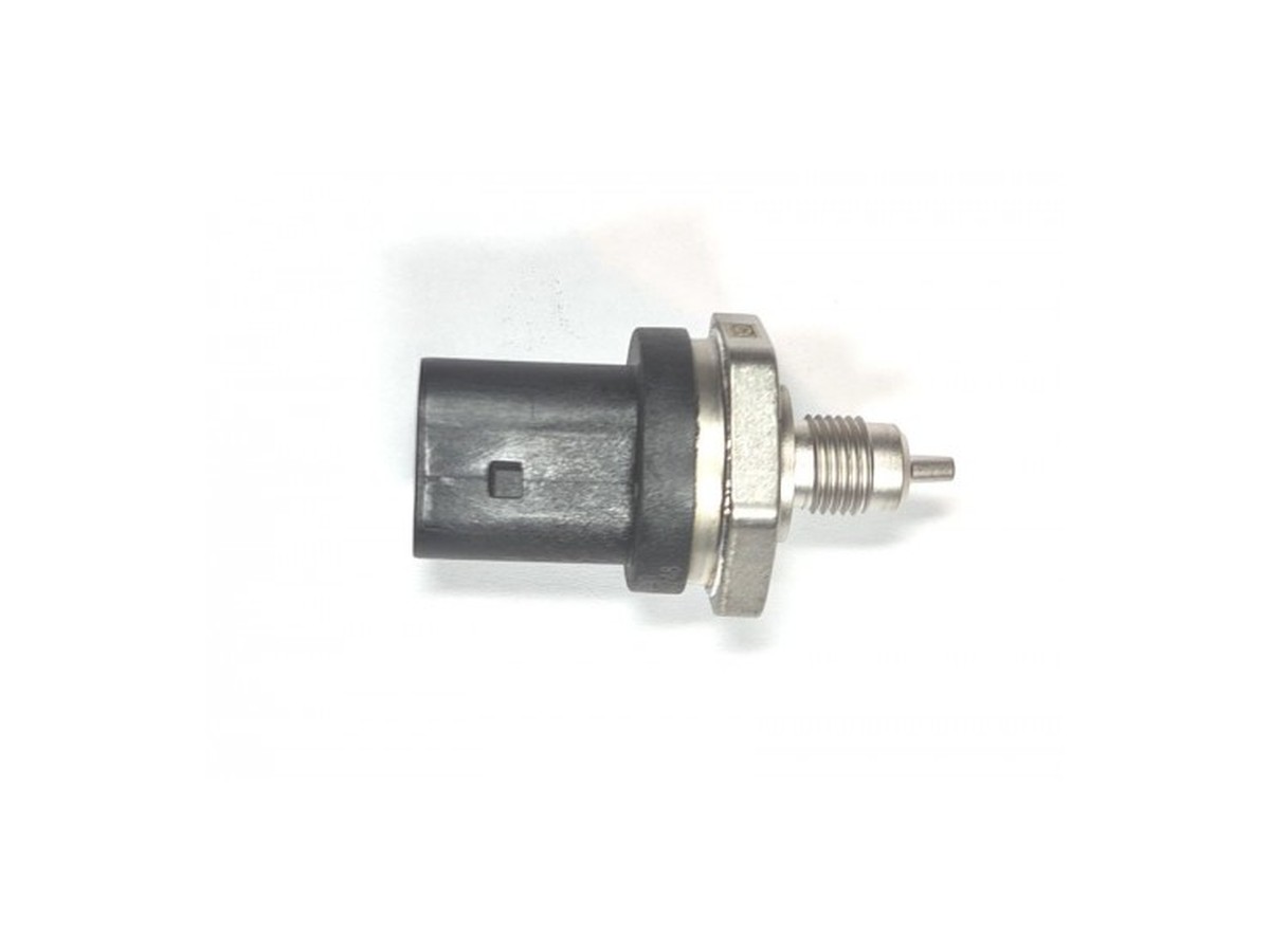
Typical parts: Bosch PST-F 1, order 0 261 544 01F (0–10 bar fluid, trapezoid). Airbox PST-1 / PST-3 / PST-4 (0 261 230 333 / 0 261 230 280 / 0 261 230 423) use a different compact connector — do not use this table for those.
Warning — Confirm the stamp. This page is the PST-F fluid family. If the hex is stamped as an airbox PST, the compact connector is pin 1 ground, pin 2 temperature, pin 3 5 V, pin 4 pressure.
Device pinout
Looking into the trapezoid, locking tab at the top. Bosch numbers the used cavities 2 · 3 · 4 · 5. Position 1 is empty. The moulded digit wins over left-to-right habit.
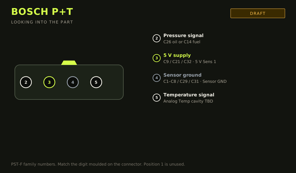
- Connector: Bosch trapezoid on the PST-F family
- Layout (looking into the part): 2 · 3 · 4 · 5; polarising key top
| Device pin | Function | Type | Race Core | TunerStudio |
|---|---|---|---|---|
| 2 | Pressure 0.5–4.5 V, ratiometric | Signal | C26 oil, or C14 fuel | Analog Volt 6, or Analog Volt 3 |
| 3 | 5 V supply | 5 V | C9 / C21 / C32 | 5 V Sens 1 |
| 4 | Sensor ground | Ground | C1–C8 / C29 / C31 | Sensor GND |
| 5 | Temperature, NTC | Signal | TBD | Analog Temp — cavity not published |
Wiring notes
- Oil pressure uses the same landing as the 3-wire oil transducer: C26, Analog Volt 6. Fuel pressure uses C14, Analog Volt 3. Do not land both jobs on one pin.
- PST-F pressure is about 0.5 V at 0 bar and 4.5 V at full scale when the supply is 5 V (about 400 mV/bar on the 0–10 bar part). Enter that pair in TunerStudio, then check it against a mechanical gauge.
- Bosch asks for about 4.6 kΩ pull-up on the temperature pin. Race Core thermistor inputs already have 2.7 kΩ on the board. Do not add a second resistor in the harness. Calibrate the curve for 2.7 kΩ, or the reading will be offset.
- Analog Temp 2 (C30) is IAT and Analog Temp 3 (C20) is CLT in this library. A third temperature cavity is TBD. Write the cavity on the lid when you use a spare thermistor input. Do not invent an AMPSEAL number.
- Thread sealant stays off the first two threads. A blocked orifice reads as a stuck pressure, not a bad calibration.
Failure modes
- Key-on pressure near 0 V or 5 V: supply and signal swapped, or the 5 V rail is dead.
- Pressure tracks, temperature sits at a rail: pin 5 open, or it was landed on Analog Volt instead of a thermistor input.
- Both readings move when the starter cranks: pin 4 is on power ground.
- A compact airbox sensor wired with this trapezoid table reads nonsense. Read the order number first.